Branch Intersections
This section describes how to effectively mask the intersections between branch levels.
Overview
The heart of any tree model is the network of branches that comprise the shape of the tree, from the trunk up to tiny twigs that sprout leaves. While custom meshes can be used as frond meshes, most branches are made out of native SpeedTree geometry that can adapt to the size and shape of each branch. At a basic level SpeedTree branches (which are one component of “Spine” generators) are cylindrical extrusions over “spines” that serve as the backbone of the branch. The user never sees the spines, only the branches or fronds that follow their shape. The skin of each branch can be modified with displacement maps and profile curves to make it more irregular.
Branch Intersections
One tricky part about this approach is getting the branch intersections to look natural. A “branch intersection” is defined as the bottom-most section of any branch at the point where it meets the parent branch. In version 6.0, we do not actually fuse the various pieces into a single “watertight” mesh. There's a lot of reason why we don't fuse them, including (for games) a large increase in polygon count, as well as for other similar practical reasons such as computation speed.
Instead, we take a few measures to ensure that the branch intersections are as unnoticeable as possible, attacking geometry, texture, and lighting seams. These measures include welding, branch intersection blending, and light seam reduction, all described below.

Welding
“Welding” is what we call our method of minimizing the geometry seams that arise when two simple cylinders are pushed together as in the following image (below left). When you look at the left side of the diagram, notice the hard intersection. On the right, the child branch has been “welded” to the trunk. This method basically allows the child to “sit” on the skin of the parent without actually intersecting the geometry.
How It Works
Welding is controlled by a group of spine generator properties in the “Branch→Welding” property subgroup. Here you set the welding distance and spread options. Distance determines how long down the branch the weld should last. “Spread” can be thought of as the web between the two pieces. An upper and lower spread are both provided. The distance profile curve also affects the way that the web shape tapers with length. Once the weld distance has been determined, the bottom segment ring is removed from the branch and the welded position of each bottom vertex is computed on the parent. Then the specified number of weld segments are computed in between. The number of weld segments are determined with the “Segments→Weld” property. If the weld distance is greater than the length of the first length segment, the second length segment may get “eaten” by the weld area, making room for the whole weld area.
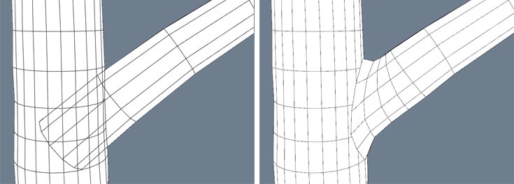
| (Left) Welding disabled. Notice the geometry intersecting it's parent. (Right) Welding enabled “sits” on its parent. |
|---|
Visualizing Weld Distance
Sometimes it can be hard to tell how the “distance” property will affect the tree. We've included a visual aid to show weld distance. Turn on “extras” either with the “extras” toolbar button, the “E” hotkey, or via the View→Extras menu. Make sure “Hints” is one of the visible extras being shown. Enter 'wireframe' rendering mode by pressing the “W” hotkey. The weld distance is visualized as a black dot on each branch. You should see the upper and lower web extend close to the black dot. As you change the Welding→Distance value up and down, the black dot should move too.
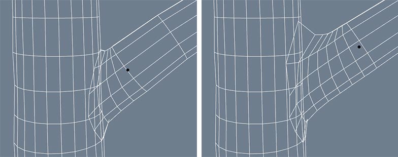
| (Left) Weld distance: 1.5, 3 weld segments (Right) weld distance: 2.2, 6 weld segments. The black dot shows the weld distance. |
|---|
Failed Welds
Sometimes, welds fail. This is almost always due to one or more of the base vertices failing to find a valid point on the parent branch. Another reason might be that the branching angle is too close to the parent branch, and the child branch does not “clear” the parent branch by the time the weld distance is reached. In these cases, the branch will appear unwelded. Often this can be fixed by entering node editing mode and node-editing the value for weld distance on a particular trouble branch.
Sometimes a weld doesn't “fail”, but it doesn't work well either. There are several properties to look at that will force the weld to recompute, possibly harboring better results. Usually, changing the start angle by rotating the branch slightly will work sufficiently. If it's important for you to not move the branch at all, try editing branch roll. Branch roll will rotate the skin component of the branch only, leaving the underlying spine in the same spot. Adjusting the sink property slightly will hide any visible gaps in the geometry, since sink is computed after welding. Past these options, changing the number of segments or the amount of displacement on either the child or parent branch may result in better welding.
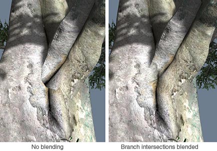
Texture Blending
Welding takes care of the geometry seams, but sometimes the intersection of the tiling textures causes more of a noticeable seam than the geometry itself. In these cases, “branch intersection blending” is used to mask the texture seam. Branch intersection blending basically takes the texture coordinates from where a welded branch hits its parent and blends those texture coordinates out after a small distance up the branch.
Getting Texture Blending Working
Branch intersection blending must first be enabled on the material asset bar on the materials that are to be blended. The two branches should share the same material. Next, welding must be enabled on the child branch generator. Not only must welding be enabled, but branch intersection blending will only be applied to branches that do not fail to weld.
Once the above criteria are met, a branch is eligible to be blended with its parent. Texture blending can still fail at this point if the child branch is growing out of a bifurcation saddle, or if there is a detail texture involved and the branch crosses a clamped texture edge. The Branch→Welding→Intersection Blending->Style property determines what to do in these cases. The default of “Standard” will only apply blending where it is likely to look good. This property can also be set to “Force”, which will make all welded branches blend no matter what. Keep in mind that this option can harbor unexpected results, since the blended texture coordinates are unpredictable.
Tuning Texture Blending
Texture blending can greatly increase the believability of your tree, but even when it succeeds it might need some tweaking. On the welded branches, first set the texture pull to the appropriate amount. “Texture pull” will streak the blended texture up the welded branch. A value of zero should be avoided since at zero the entire base ring is pulling towards the same point in texture space. Adjust this value until the aspect ratio of the blended area matches the parent branch.
Next, edit the blending offset. The blending offset adjusts the “line” between the blended and non-blended parts of the welded branch. adjust the blend fade with this value once you are happy with the texture coordinates. One final tuning option is the “weight” value, set on the material. The “weight” doesn't adjust the fade line, but it does affect how “dense” the blend area is in the blend computation. Higher weight values favor the blend area.
Rendering Outside of The Modeler
It's great that intersection blending works in the Modeler, but what about rendering the effect outside of our app? With SpeedTree For Games, our SDK already supports the effect. It can be faded off with effect LOD in the SpeedTree Compiler as well.
SpeedTree Studio/SpeedTree Cinema customers can get the data out via our FBX exporter. Make sure to check the option for “include branch blending”. The blending data is saved out in texture layers 3, 4, and 5 (if detail textures are present). This data can be interpreted In 3ds Max, Houdini, Cinema4D, or Maya via import scripts and incorporated into the native shaders in each of those apps.
Light Seam Reduction
The last type of seam that may be visible is a “lighting” seam. Lighting seams are caused by the normals of the two intersecting branches. We have a few properties that make for progressively improved lighting seams, as seen below:
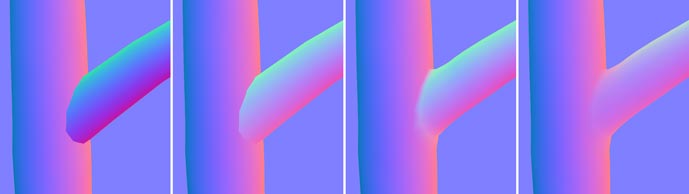
| (A) No light seam reduction, (B) Light seam reduction of 0.5, (C) Welded with reduction, (D) Welded with “normal blending” |
|---|
Reducing Lighting Seams
 Light seam reduction is present even if branches aren't welded. The above left-most picture shows a standard cylindrical branch without light seam reduction. The intersection is very jarring. By increasing the light seam reduction to 0.5, the normals of the intersecting branch blends with the direction the branch is growing.
Simply enabling welding at this point will further reduce lighting seams. But it can be taken a step further. The third image above shows welding with a normal blending curve set to the “min” preset (no normal blending). Normal blending is an extra measure that can only be applied to welded branches, where the normals are interpolated with those where the weld meets the parent. By default, it will already have an effect similar to the right-most image, which represents an ideal case of light seam reduction (they are not visible at all).
| Keep in mind that the normal blending curve has an effect on *any* welded branch, even if it is a trunk. If you are welding your trunk to the terrain, make sure to set the normal blending curve to the “min” preset so that the default normals are used on the trunk. |
|---|
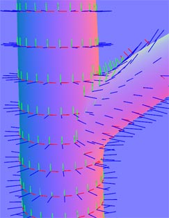
Displaying Normals
In the above screenshots, the “Geometry normal map” rendering mode was enabled to see a visualization of the normals as colors. (Located in the Render Tab on the Tree Window Toolbar) If you find it easier to view the actual geometry normals instead of a color encoding (as seen to the right), you can turn on normals as an “extra” under the menu item View→Extras→Normals or with the “Extras” menu button on the Tree Window toolbar.